Common Reasons a 13.56MHz NFC Antenna Fails to Reach Its Rated Range in Real Use
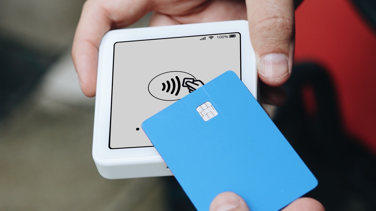
Rated read range figures for NFC antennas and tags are derived from lab conditions: matched impedances, optimal coil alignment, no interfering materials, controlled temperature. In practice, most deployments encounter some combination of conditions that differ from those assumptions. The result is read range that falls short of what the specification suggests — sometimes by a small margin, sometimes dramatically. The engineering work of diagnosing why a 13.56MHz NFC antenna underperforms follows a fairly consistent set of root causes.
Impedance mismatch and the detuning problem
NFC inductive coupling operates by resonance. The reader antenna and the tag coil each form part of a tuned circuit, and maximum energy transfer occurs when both sides are resonating at 13.56 MHz. When either antenna is detuned — when its resonant frequency shifts away from 13.56 MHz — coupling efficiency drops and read range decreases proportionally.
Detuning happens for several reasons. Component tolerances in the matching network capacitors shift the resonant frequency slightly from the design target. This is manageable if the tolerance stack stays within the passband, but with ±5% capacitor tolerances, a batch of antennas can have center frequencies spread across several hundred kHz on either side of 13.56 MHz. Tighter component tolerances narrow this spread.
More significantly, the proximity of conductive or dielectric materials changes the antenna’s effective impedance after it’s assembled into a product. An NFC coil tuned in isolation may be substantially off-resonance once it’s mounted in a plastic housing with a metal battery pack two centimeters away. The matching network should be finalized in the as-installed configuration, not on the bare coil, to account for these loading effects.
Tags face the same issue from the other direction. NFC tags embedded in products — on-metal tags on tool assets, tags inside glass bottles, tags laminated into fabric — are exposed to detuning from the substrate material. On-metal tags use ferrite substrate layers to isolate the coil from the metal; standard inlay tags placed directly on metal will be severely detuned and may not respond at all.
Coil alignment and the coupling efficiency falloff
NFC coupling is strongest when the reader and tag coils are coaxially aligned — centered on the same axis with parallel planes. As the tag moves off-center or tilts relative to the reader, coupling efficiency drops. The falloff is sharper than most users expect.
A tag that reads at 8cm when centered on the reader may only read at 3cm when offset by 2cm laterally, because the coupling coefficient between the coils decreases rapidly with misalignment. In applications where users place a card or phone on a reader pad, the position variability determines the effective read range — not the maximum range under ideal alignment.
This affects product design decisions. A larger reader antenna coil provides a wider zone of usable coupling, at the cost of reduced coupling strength at close range. A smaller, high-inductance coil reads better at the center but has a sharper falloff at the edges. Matching the reader coil geometry to the expected tag presentation variability is part of the antenna design, not just the matching network.
For smartphone NFC, this matters differently. The NFC antenna in a phone is typically offset from the phone’s center to avoid overlap with the camera array or battery. Knowing where a phone’s NFC antenna is physically located — which varies by manufacturer and model — affects where a reader should be positioned on a surface for reliable reads across a mixed population of devices.
Multi-tag collision and read failure in dense environments
NFC’s anti-collision protocol (ISO 14443-3 for Type A and Type B tags) allows a reader to inventory multiple tags in its field by assigning each a unique identifier during a collision resolution sequence. However, when many tags are simultaneously within the reader’s field, the collision resolution process takes time, and some implementations have limits on how many tags can be resolved reliably in a single poll cycle.
In library systems, retail inventory, or document tracking applications where many tagged items may be in a stack or bin, apparent range failure — where the reader “misses” individual tags — is often actually a collision handling issue rather than a coupling problem. The tag is within range and responding, but its response is being overwritten by simultaneous responses from neighboring tags.
Reducing field strength to limit the number of simultaneously active tags can counterintuitively improve read reliability in dense scenarios, by narrowing the active zone to a smaller subset of tags at one time. Application-level software that retries reads and builds a complete inventory over multiple polls is more robust than a single-shot approach that expects to capture all tags in one cycle.
Cable loss and connector degradation in reader-antenna systems
In NFC reader systems where the antenna is separated from the reader electronics by a coaxial cable — embedded kiosks, panel-mount readers in equipment enclosures — the cable and its connectors are part of the RF signal path. At 13.56 MHz, cable loss is low compared to higher frequencies, but connector quality matters more than it appears.
Oxidized or poorly made SMA or MCX connectors add insertion loss that reduces the field strength at the antenna. In humid environments or installations where connectors are exposed to condensation, connector degradation accumulates over months. A system that performs well at installation and gradually deteriorates over time without any other change is often explained by connector degradation in the antenna feed path.
Checking connector resistance and inspecting for oxidation is a maintenance step that gets overlooked in NFC reader deployments because the connection is made once during installation and then forgotten. For long-term deployments, specifying gold-plated connectors and sealing the connection from moisture is worthwhile.
Firmware and protocol stack issues that appear as antenna problems
Some read failures that present as range problems are actually software issues. An NFC reader polling at too-long intervals may miss a tag that’s only in the field briefly. A reader configured for one tag type (ISO 14443 Type A) will not detect tags of another type (Type B or ISO 15693) even if they’re physically within range. A reader with an aggressive timeout setting may abandon a read attempt before the tag has responded.
Before concluding that a range shortfall is an antenna or tuning problem, verifying that the reader firmware is correctly configured for the tag type in use, that polling rates match the expected tag presentation speed, and that protocol timeouts are set appropriately for the application eliminates the software layer as a variable.
For a 13.56MHz NFC antenna, the diagnostic path follows this order: confirm the antenna is resonating at 13.56 MHz in the installed configuration, verify coil alignment with the expected tag presentation geometry, check for metal proximity effects and add ferrite shielding if needed, inspect connectors for degradation, and validate firmware configuration for the tag type in use. Each step eliminates one category of root cause. The one that produces improvement is the actual problem — and it’s rarely the last one checked.